Search:
BACKGROUND OF STRESSED STATE MAGNETIC INSPECTION
OF STEEL PARTS BY METAL STRESS INDICATORS
OF STEEL PARTS BY METAL STRESS INDICATORS
Common physical principle of nondestructive testing of stressed state of metal based on dependence so called structural sensitive parameters of metal on mechanical stresses.
Residual magnetization of metal Jr is one of these parameters, most sensitive to mechanical stresses and susceptibility to their variations.
Magnetization appears in steel sample under exposure of magnetic field. At strong fields like HS, magnetization value can reach practical limit JS, appropriate magnetic state of sample also called as technical saturation (fig.1). After the magnetic field action was switched off the metal would remain in the magnetized state, which is characterized quantitatively by residual magnetization Jr.

Fig.1. Change of steel sample magnetization J under action of constant magnetic field H
O1-3 – initial magnetization of metal in the Earth magnetic field;
HS – applied magnetic field strength enough to magnetize sample up to technical saturation state, quantitative parameter of which is saturated state magnetization JS;
Jr – residual magnetization of sample after the magnetic field action was switched off;
HC
– coercive force
In metal stress indicators magnetizing unit excites magnetization of inspected object, then measuring unit measures residual magnetic field strength (induction) on the surface of inspected object, which is, in essence, response of metal on magnetization unit action.
In relation to mechanical stresses residual magnetization of metal can appear itself as two principally different physical parameters, in dependence of environmental conditions and order of their influence on residual magnetization organization process.
Condition I. When an elementary volume of the metal already loaded constantly is magnetized, the following ratio would be hold between its general magnetic parameters:
![]() , (1)
, (1)
where are
χ –
is magnetic susceptibility of metal, λS – is magnetostriction of the saturated metal, JS – is magnetization of the metal saturated, σ – is mechanical stress, μ0 – is the magnetic constant.
For the right triangle O-Jr-HC on the figure 1 the geometry equation ![]() is true. Insertion of one into the formula (1) will result to the following expression:
is true. Insertion of one into the formula (1) will result to the following expression:
![]() . (2)
. (2)
The formula (2) obtained includes the two parameters are depending on mechanical stress of metal: Jr
and НС. In order to exclude last one of recent form the formula (2) we can use the symbolic relation between coercive force and residual magnetization of the metal is known:
 , (3)
, (3)
where are
Jr0 – is residual magnetization of metal without another mechanical stress (idealσ = 0). Inserting expression (3) into (2) and keeping in the mind that for constructional steels is usually Jr <<
JS (see to the figure 1), obtain the dependence of residual magnetization on the mechanical stress of the metal, caused to constant loading:
![]() . (4)
. (4)
The residual magnetic field strength of metal, measured by metal stress indicators, is directly proportional to residual magnetization, herewith the value of one is also depends on the shape of surface inspected: Hr(s) = Jr(s)·TF(x, y, z).
A topographic factor TF(x, y, z), describing the surface of metal inspected is always remain constant, so the Hr(s) dependence is looks as following:
![]() . (5)
. (5)
In general the σ parameter would be considered as an effective mechanical stress of metal, which is determined by theory of the durability and strength of materials through components of principal stresses and Poisson ratios:
![]() . (6)
. (6)
In the case of linear (one-axial) stressed state of metal (σy = 0 σz = 0) an effective
stress is equal to the one component of principal stresses:![]() .
.
On the figure 2 an experimental dependences of residual magnetic field strength of metal presented are obtained in linear (one-axial) loading of steel specimens made from constructional steel, widely used in the industry, which are in agreement with symbolic expression (5).
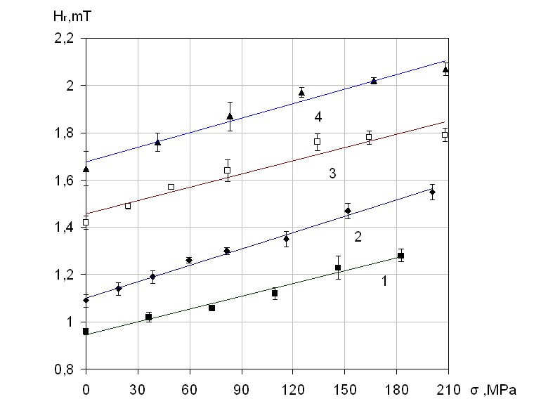
Fig.2. Dependences of residual magnetic field strength of steel part already under load on the mechanical stress of metal
1 – St37-2 specimen (DIN), 2 – RSt37-2, 3 – 9MnSi5, 4 – St52-3G
In the case of plane (two-axial) stressed state of metal σz = 0 an effective
stress is looked as ![]() , so the expression (5) will be reduced to following:
, so the expression (5) will be reduced to following:
 . (7)
. (7)
An expression (7) obtained could explain that the behavior of residual magnetic field dependence Hr on the components of principal stresses σx and σy is determined by relation between their signs:
– If the components of principal stresses σx and σy
are in opposite signs then the sign before Poisson ratio in the formula (7) would be positive, so the dependence Hr(σx, σy) would have unique, however non-linear behavior (see the figure 3,
σx /σy < 0);
– If the components of principal stresses σx and σy
are in one sign then the sign before Poisson ratio in the formula (7) would be negative, so the dependence Hr(σx, σy) would have not unique (see the figure 3, σx /σy > 0).
σx /σy < 0 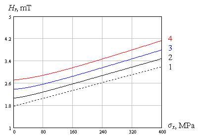
|
σx /σy > 0 |
Fig.3. The influence of relation between signs of
σx and σy the plane stressed state components of metal to residual magnetic field Hr dependence on ones
1 – σy = 0 MPa, 2 – 40 MPa, 3 – 80 MPa, 4 – 120 MPa
Condition II. When an elementary volume of the metal preliminarily magnetized to technical saturation is caused to loading, the demagnetization of one would occur due to magnetoelastic effect. So the residual magnetic field strength of metal while the metal is in elastic state would be changing on reverse dependence:
 , (8)
, (8)
where is
σ in general would be considered as an effective stress of metal (6), which is in the case of linear (one-axial) stressed state of metal (y = 0 z = 0) equal to the one component of principal stresses: ![]() .
.
On the figure 4 the residual magnetic field strength of metal changing under linear (one-axial) loading of preliminarily magnetized steel specimens, made from constructional steel, widely used in the industry, which are in agreement with symbolic expression (8).
In the case of plane (two-axial) stressed state of metal z = 0 an effective
stress is looked as ![]() , so the expression (8) will be reduced to following:
, so the expression (8) will be reduced to following:
 . (9)
. (9)
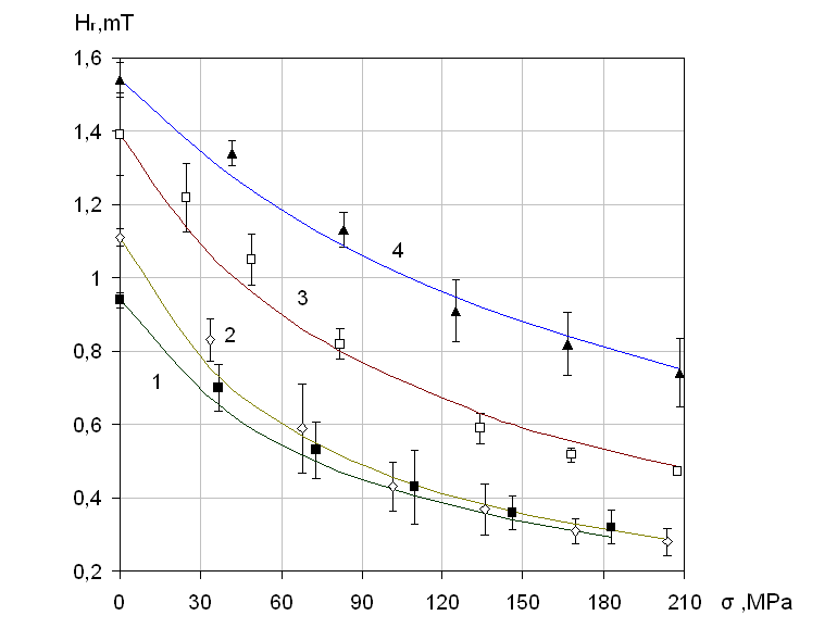
Fig.4. A behavior of the residual magnetic field strength when preliminarily magnetized steel part is loaded by constant monotonically increased force
1 – St37-2 specimen (DIN), 2 – RSt37-2, 3 – 9MnSi5, 4 – St52-3G
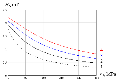
An expression (9) obtained could explain that the behavior of residual magnetic field dependence Hr of the metal preliminarily magnetized on the components of principal stresses σx and σy is determined by relation between their signs (see to the figure 5).
σx /σy < 0
σx /σy > 0
|
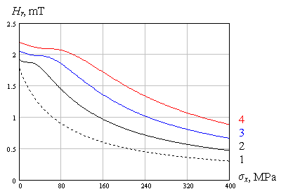 |
Fig.5. The influence of relation between signs of σx and σy the plane stressed state components of metal to behavior of residual magnetic field Hr change in two-axial loading of metal preliminarily magnetized
1 – σy = 0 MPa, 2 – 40 MPa, 3 – 80 MPa, 4 – 120 MPa
So, creating the different initial conditions in the practice we can to observe how the residual magnetic field strength of metal Hr measured by the metal stress indicators IN-01m and IN-02 behaves as two different physical parameters:
1. When steel part already loaded constantly is magnetized, the residual magnetic field strength Hr would depend linearly on effective value of mechanical stress of the metal σeq; so this dependence on the components of principal stresses σx and σy is determined by relation between their signs.
2. When steel part preliminarily magnetized to technical saturation is caused to loading, the residual magnetic field strength Hr while the metal is in elastic state would be changing on reverse dependence.

Fig.6. The strain gage bench of SPECTOR Sci-Tech LLC for experimental investigation of two-axial stressed state of metal
1 – the cruciform steel specimen investigated, 2 – power screws, 3 – strain gages assemblies, 4 – conditioning and measuring unit
Recently the specialists of SPECTOR Sci-Tech LLC are carrying out the experimental investigation to approve the theoretical dependences of residual magnetic field strength Hr on the components of principal stresses σx and σy obtained in the strain gage bench shown on the figure 6 which is created especially for this purpose.