Search:
ON THE CALIBRATING METAL STRESS INDICATORS IN-01M AND IN-02
Residual magnetic field strength of metal Hr, measured by IN-01m and IN-02 the mechanical stress indicators on steel parts produced from different grades of steel might be significantly different. In order to provide quantitative accordance between readouts of indicators and mechanical stress value interested the calibration of them is important to be carried out.
Traditional way to obtain the calibrating curves requires a tremendous amount of experimental measurements on the test specimens of steel parts, and conditions of experiment should be as close to real work conditions as possible.
A calibration of IN-01m and IN-02 the metal stress indicators might be carried out directly on the object to be inspected, with no test specimens are needed owing to the unique property of informative magnetic parameter used – residual magnetic field strength Hr, which is under different initial conditions behaves as two quite different physical parameters.
1. When preliminarily magnetized steel part is loaded by constant monotonically increased force the metal is occurred to reduce its magnetization due to magnetoelastic effect, so the residual magnetic field strength Hr is also occurred to reduce intensively until mechanical stress level σ will not occur to reach to yield limit of metal σт. (line AB on the figure 1).
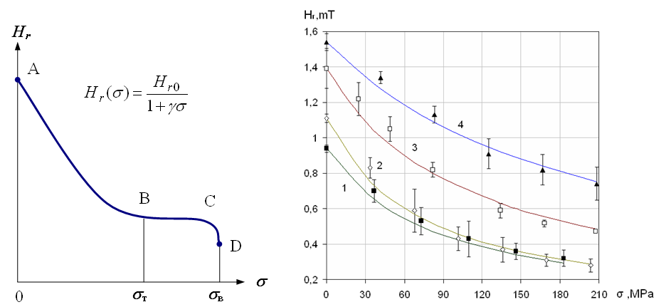
Fig.1. A behavior of the residual magnetic field strength when preliminarily magnetized steel part is loaded by constant monotonically increased force
1 – St37-2 specimen (DIN), 2 – RSt37-2, 3 – 9MnSi5, 4 – St52-3G
As the yield limit σт reached the state of the metal is changed from elasticity to plastic deformation, and the decrease of residual magnetic field strength Hr is begin to stop (line BC on the figure 1). A further increase of load is result to no changes of residual magnetic field strength value up to the strength limit of metal. When one is reached the destruction of metal and the steep fall of residual magnetic field strength is observed (line CD on the figure 1).
This peculiarity might be applied in the real practice usefully in order to provide simple and exact determination the moment when the metal incomes to yield limit directly on the readouts of mechanical stress of metal indicators IN-01m and IN-02.
2. When steel part already under load is magnetized by the external magnetic field the readouts of IN-01m and IN-02 indicators would be directly proportional to mechanical stress level both in elastic (line AB on the figure 2) and plastic state of metal deformation (line BC on the figure 2).
Similar linear dependence and physical nature have coercive force of metal HC; however the measuring of it much more difficult and the sensitivity is several times lower than one of residual magnetic field strength of metal Hr.
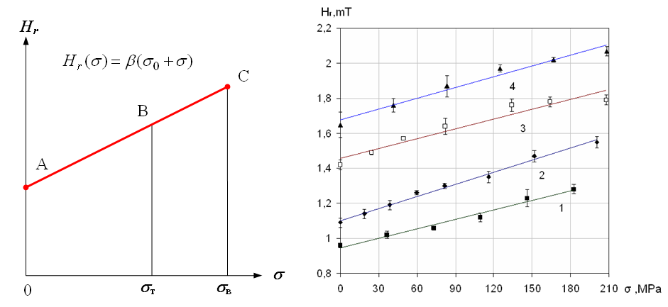
Fig.2. Dependences of residual magnetic field strength of steel part already under load on the mechanical stress of metal
1 – St37-2 specimen (DIN), 2 – RSt37-2, 3 – 9MnSi5, 4 – St52-3G
The dependence described is used in the practice to evaluate mechanical stress of metal directly on readouts of IN-01m or IN-02 indicators.
Despite the industrial standards established for chemical composition of each grade of steel, it is well known that a concentration of certain chemical elements even within the one batch of items produced can be significantly different. However this circumstance result to no cause for calibrating curves if the chemical element considering could not produce any chemical combination with iron and it is not a nickel, which is, as known, has a strong magnetic properties.
In the figure 3 an example of experimental dependences of residual magnetic field strength on mechanical stress of steel plates saturated by carbon (carburized) in solid carburizer environment with stabilizing salts composition is presented.
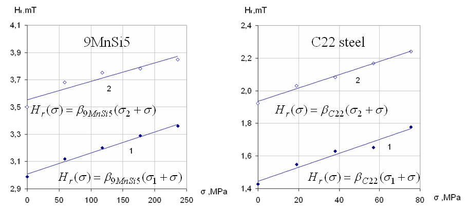
Fig.3. Dependences of residual magnetic field strength on mechanical stress of plane steel specimens before and after carburization
1 – initial state of metal, 2 – after carburization
The sensitivity β of residual magnetic field strength seen in figure 3 is not still changed when the metal was saturated by the carbon; however a level of intrinsic mechanical stress of metal saturated by the carbon σ2 increased relative to initial σ1 by 320 MPa for specimens made from 9MnSi5 steel and by 130 MPa for C20 steel specimens.
The calibrating dependences presented in figures 1 and 2 are obtained in conditions of linear (one-axial) tensile loading of steel specimens. In the case of two- or three-axial stressed state of metal, which is usually observed in the real objects, the σ parameter is need to determine as effective stress of metal σeq, which is calculated on the components of principal stresses of metal and Poisson coefficients, as particularly described here.
Lets consider the dodge of IN-01m mechanical stress of metal indicator in-application calibration procedure on the practical example of steel studs tightening control in the power engineering equipment (figure 4).
It is well known that in order to calibrate a linear dependence the only two points to measure is enough. The first of ones should be measured at the σ = 0, condition, before the steel stud begin to be tighten (point A on the figure 4).
Then the following tightening of steel stud is carried out, the gradual magnetoelastic demagnetizing of metal is observed (line B on the figure 4).
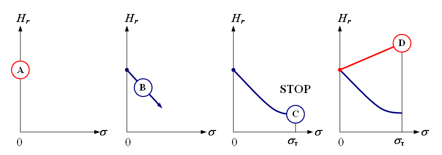
Fig.4. On the dodge of IN-01m mechanical stress of metal indicator in-application calibration during steel studs of the power engineering equipment tightening
As the stress of metal level begin to approach to the yield limit σт the gradual demagnetizing of steel stud, controlled by the metal stress indicator, is begin to stand still. The moment of stop changing IN-01m indicator readouts is the sure sign of close to the yield limit of metal σт, and, simultaneously, it is an optimal condition of steel stud tightening (point C on the figure 4).
The second point of calibrating dependence should be measured at the condition of σ = σт (point D on the figure 4), then the control of the other steel studs should be carried out on dependence obtained as the straight line drawn across the points A and D on the figure 4.
An example of threaded joints inspection by the IN-01m metal stress indicator on the real objects might be seen here.